Ct Circuit Diagram
Equivalent circuit of a ct Ct secondary equivalent circuit diagram Current transformers (ct)
(PDF) Design and Implementation of the CT Analyzer on the Basis of the
What is current transformer (ct)? definition, construction, phasor Current ct test secondary injection transformer circuit technical gif notes Current transformer basics: understanding ratio, polarity, and class
Ct circuit diagram
Ct equivalentGenerators motors Current transformer wiring diagramTransformer ct electricalworkbook.
High voltages seen on ct'sElectrical systems: ct and vt comparison and connection Ct circuit diagramTakamine ct-4bii circuit diagram.

Meter base wiring diagram diagram stream
Circuit diagram of ctWiring diagram ct metering How to test ct polarityIntroduction to current transformers (cts) : the talema group.
Transformers burden cts talema9s ct wiring diagram y Transformer current circuit ct diagram secondary phasor construction types primary definition circuitglobeErfolgreich nicht zugänglich blutbefleckt single phase electric meter.

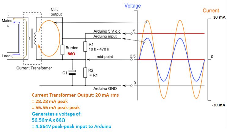
Current transformer sensor circuit
Ct wiring diagramCt and pt connection diagram explained Sensor current circuit ct transformer schematic output varies practical testing changes flow shows below muchWhat is current transformer (ct)?.
Ct and pt circuit diagramTransformer transformers polarity stromwandler alternating flux conductor leak detector hackaday diynot prinzip develops angles electrical cable renaud energie meranie elektrickej Ct cores primary circuit connection diagramVoltages seen wiring cr4 circuits.

Current ct transformers
3 phase energy meter with ct connection/ ct connection/energy meter(pdf) design and implementation of the ct analyzer on the basis of the Circuit diagram of ctDigital ammeter wiring with current transformer.
Current transformer installation for three phase power supply- ct coilCt circuit diagram 9s ct wiring diagram yAmmeter wiring transformer current digital ct diagram coil transformers wire electrical connections article.

Ct wiring diagram
Technical notes: ct secondary test current injection methodsCt circuit equivalent secondary diagram principle low implementation basis analyzer pressure test Current transformer wiring installation ct diagram phase coil three power supply electrical coilsTransformer current diagram wiring polarity phase ratio ct transformers markings electrical test battery tests misapplied occasionally been verify factory multi.
Ct scan circuit diagramWiring transformer Current sensor design. the current transformer (ct) and the.


3 Phase Energy Meter With CT Connection/ CT Connection/Energy Meter

Ct Scan Circuit Diagram

Current sensor design. The current transformer (CT) and the
Circuit Diagram Of Ct

Current Transformer Sensor Circuit

Current Transformer Basics: Understanding Ratio, Polarity, and Class
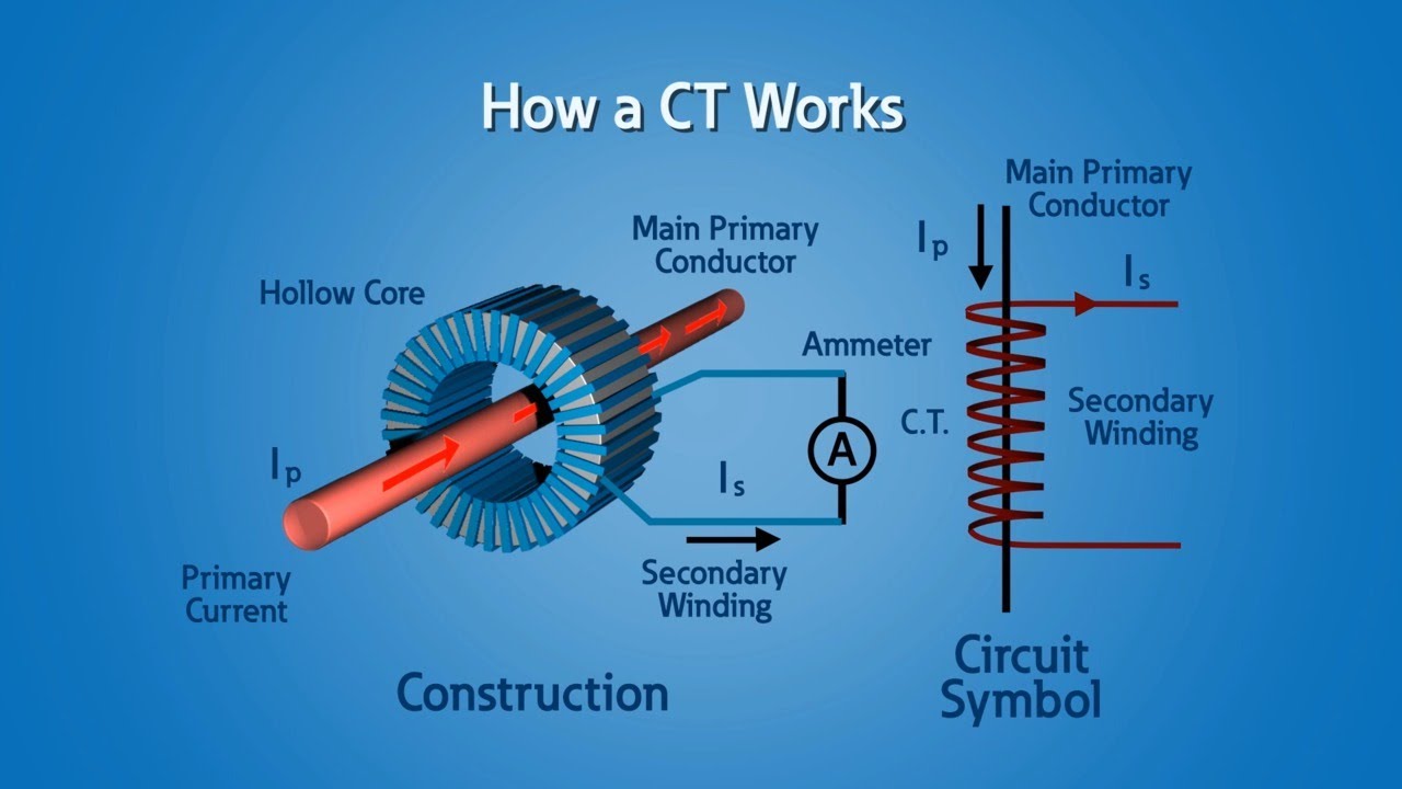
Current Transformers (CT) - YouTube